Eye-to-eye body
Compact configuration with spherical-eye connections at both ends. Installation length, pin size and articulation are checked against the support steel and piping attachment.
YZN hydraulic snubbers are designed to allow slow thermal movement with low resistance, then restrain rapid displacement caused by a dynamic event. Catalogue data is used for RFQ screening; the project load, stroke, connections and installation geometry control final selection.
Send Snubber RFQ Data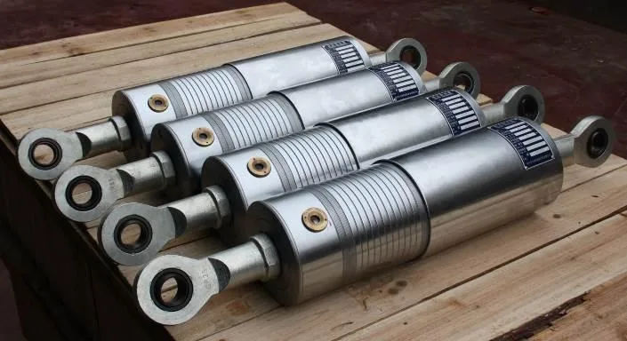
YZN hydraulic snubbers allow slow thermal movement and restrain rapid displacement in piping systems. Damper is a broader term: it does not establish that a device has the same operating principle or is interchangeable with a pipe snubber. This page describes the YZN hydraulic snubber range, not mechanical snubbers or a separate range of viscous dampers.
A valve-controlled hydraulic piston permits fluid transfer during slow movement, helping the attached piping or equipment follow normal thermal displacement. When piston speed rises above the set lockup threshold, the hydraulic path closes and the unit develops restraint force that transfers the dynamic load to the supporting structure.
Typical design cases can include water hammer, steam hammer, fast valve closure, seismic action, wind load or impact. The required event, load case, stroke and attachment geometry must come from the project analysis or controlling drawing; a catalogue range is not a substitute for that input.
| Code block | Meaning in the 2026 catalogue | RFQ control |
|---|---|---|
| YZN | Hydraulic snubber family | Confirm required dynamic-restraint function |
| S / D | Vibration / safety-valve discharge function code | Select only from project duty and drawing |
| 100 | Example bore size, mm | Do not select from pipe size alone |
| 150 | Example stroke, mm | Check movement envelope and installation allowance |
| W | With extension rod | Confirm installed length and connection arrangement |
| Bore | Catalogue normal load | Pin diameter |
|---|---|---|
| 25 mm | 5 kN | 10 mm |
| 32 mm | 10 kN | 12 mm |
| 40 mm | 16 kN | 15 mm |
| 63 mm | 48 kN | 25 mm |
| 80 mm | 80 kN | 35 mm |
| 100 mm | 120 kN | 40 mm |
| 125 mm | 200 kN | 50 mm |
| 160 mm | 320 kN | 60 mm |
| 200 mm | 500 kN | 80 mm |
| 250 mm | 1000 kN | 100 mm |
Compact configuration with spherical-eye connections at both ends. Installation length, pin size and articulation are checked against the support steel and piping attachment.
Extension-rod configuration for longer installation envelopes. The required stroke allowance remains separate from installation-length adjustment.
Flanged extension arrangement where the approved project connection requires it. Flange, fastener and interface details stay drawing-controlled.
| Input | Why it matters | If missing |
|---|---|---|
| Required function / dynamic event | Defines what the restraint is expected to react against | Keep model selection open |
| Normal load and governing load case | Controls the catalogue group and attachment loads | Do not infer from pipe diameter |
| Required stroke and movement direction | Controls body and rod travel allowance | Request stress-analysis output |
| Cold installation length | Controls compact or extension arrangement | Request dimensioned field or drawing record |
| Orientation and connection details | Controls pin bracket, eye and structural interface | Request marked-up support detail |
| Service environment | Controls materials, sealing, coating and inspection scope | Keep finish and seal arrangement TBC |
| Testing and documentation requirements | Controls inspection plan, records and witness points | Do not assume certification or report scope |
The photographs below document finished cylindrical units, a damping device in a factory test rig and an anonymized field installation. They support product-family and manufacturing-experience statements only; they do not prove the model, load, test result or project qualification of a particular RFQ.
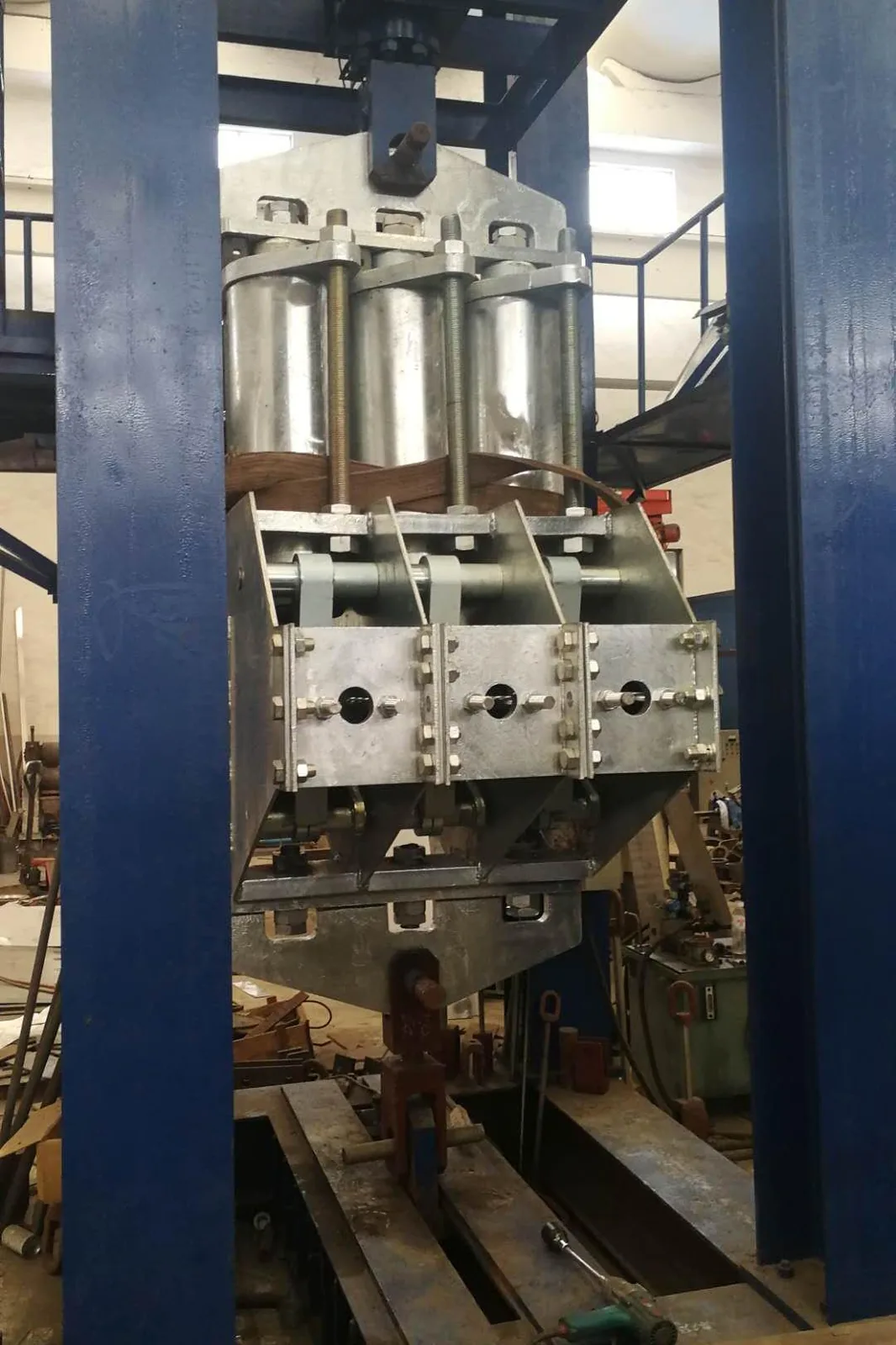
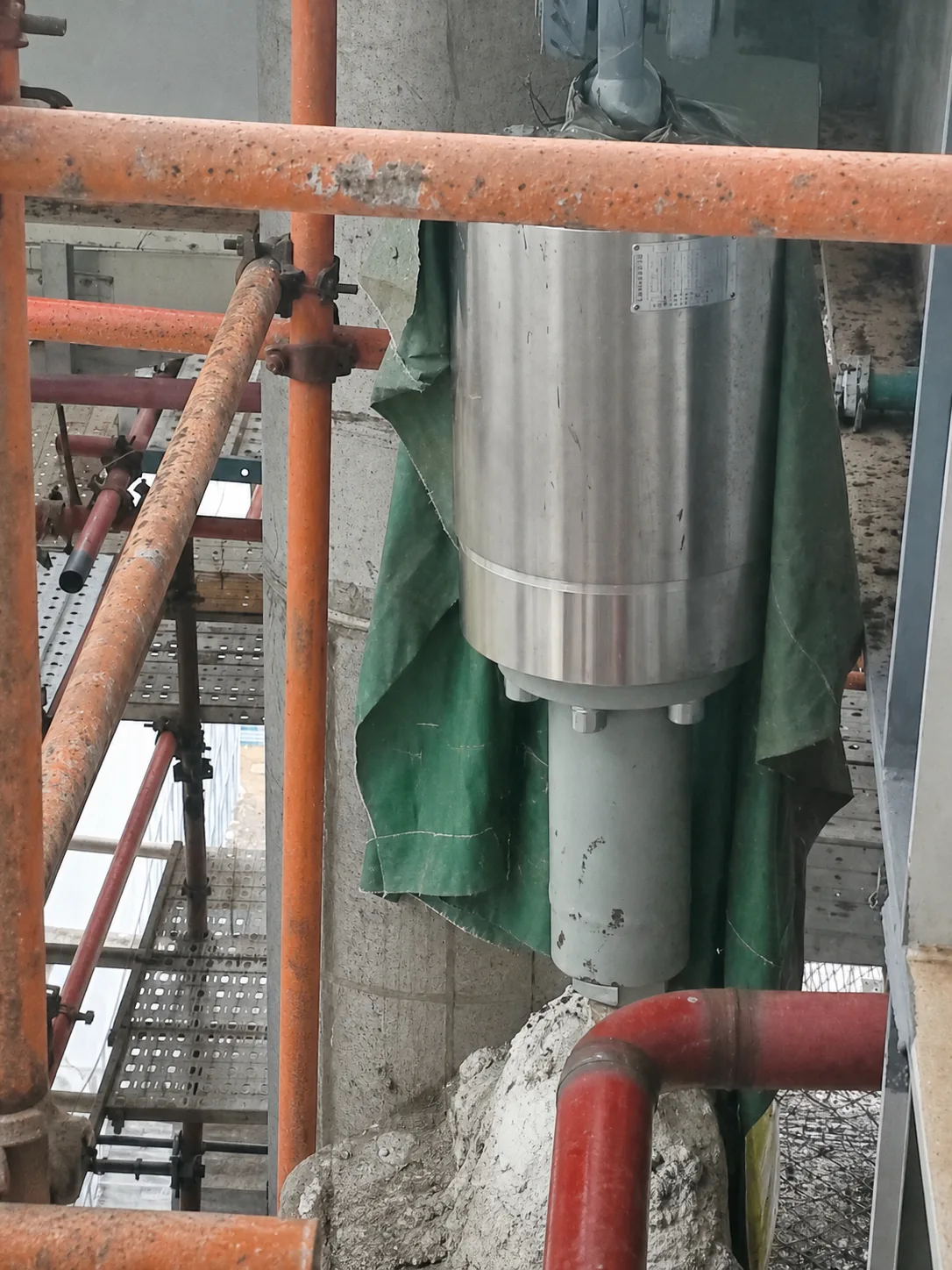
See the complete factory and field evidence record and the manufacturing and inspection equipment register summary.
This YZN product family is a hydraulic snubber: it is intended to permit slow thermal displacement with low resistance and restrain rapid displacement above its velocity setting. Some RFQs use hydraulic damper as a broader or informal term, but dampers and snubbers should not be treated as interchangeable without checking the required function.
Provide the required function, normal load, stroke, installation length, orientation, connection and pin details, service environment, piping displacement information and the controlling drawings. Final model and dimensions are confirmed against that project input.
The 2026 YZN catalogue lists normal loads from 5 to 1000 kN across bore sizes from 25 to 250 mm. These are catalogue reference values, not an automatic selection or project-specific capacity confirmation.
No. ASME OM uses the industry category dynamic restraints (snubbers), but this page does not claim ASME certification, nuclear qualification or a project test result. Certification, testing and documentation scope must be confirmed before quotation.
Send the load case, stroke, installed length, connection detail, environment and drawings for project selection.