Clevis Hanger vs Pipe Clamp: A Technical Comparison for Buyers
Quick answer: a clevis hanger supports a horizontal pipe from an overhead rod through a hanger body beneath the pipe. A pipe clamp surrounds or grips the pipe and connects it to the rest of the support assembly. A riser clamp is arranged around a vertical pipe and transfers support through lateral arms or lugs. These names describe different component patterns, but they are not complete selection instructions.
The correct choice comes from the project support detail: pipe orientation, the intended support or restraint function, the connection above or beside the pipe, pipe outside diameter, insulation, movement inputs, material, finish and the controlling drawing revision. A catalogue photo can help identify a family; it cannot replace those design inputs.
This guide explains how to compare the four patterns most often confused in schedules and enquiries: clevis hangers, two-bolt pipe clamps, three-bolt pipe clamps and riser clamps. It focuses on how an engineer or buyer should read the available evidence before selecting, specifying or requesting a quotation.
Why these product names are often confused
The names overlap because all four components sit close to the pipe and may appear as curved steel bodies with bolts. In a photograph without the rod, supporting steel or pipe orientation, one pattern can be mistaken for another.
The more useful question is not “Which product looks closest?” It is “How does this detail transfer the pipe reaction into the supporting structure?”
That question separates three interfaces:
- Pipe interface: where the component touches, surrounds or supports the pipe.
- Connection interface: where the component connects to a rod, lug, beam, floor opening or other support steel.
- Project interface: the drawing, line list, insulation specification and design inputs that control dimensions and materials.
If any of these interfaces is missing, the component name alone is not enough for a final selection.
Clevis hanger vs pipe clamp: the main structural difference
Clevis hanger
A clevis hanger is normally shown below a horizontal pipe, with an upper connection to a threaded rod. Its visible body supports the pipe and transfers the reaction upward into the rod connection.
On a support detail, check:
- Whether the line is horizontal.
- The upper rod and connection geometry.
- The pipe seat or contact arrangement.
- The controlling pipe size or actual outside diameter.
- Whether an insulation shield, saddle or separate protection detail is shown.
- The required material, finish and drawing revision.
The term “clevis hanger” does not by itself establish a load rating, rod size, temperature limit or standard type number. Those must be confirmed from the project specification and the selected design.
Pipe clamp
A pipe clamp is shown around the pipe. Depending on the project detail, the clamp body may connect to a rod, lug, trunnion or other support member. The closing fasteners hold the clamp pattern together, but their number is only one identification clue.
On a support detail, check:
- Whether the clamp is suspended, seated or connected laterally.
- The location and geometry of the attachment point.
- Pipe size or actual outside diameter.
- Whether the clamp contacts bare pipe, a shield or another specified interface.
- Insulation thickness and the required clearance or envelope.
- Material, fastener requirements, finish and project drawing reference.
A clamp should not be chosen by bolt count alone. Two details with similar-looking clamp bodies may have different dimensions, attachments or service requirements.
Riser clamp
A riser clamp is associated with a vertical pipe detail. Its lateral arms or lugs form the visible interface with the supporting floor or steel arrangement.
On a riser detail, confirm:
- The pipe is vertical at the support location.
- Where the clamp arms bear or connect.
- The support elevation and available interface.
- Pipe size or actual outside diameter.
- Insulation or contact details, if present.
- Material, finish, quantity and drawing revision.
The presence of lateral arms helps identify the family, but it does not provide the support load or prove that the surrounding structure is adequate. Those remain engineering inputs.
Four patterns compared by drawing evidence
The table below is an identification and specification aid. It is not a load-selection chart.
| Pattern | Pipe orientation usually shown | Visible drawing clues | Reaction path to verify | Inputs that remain project-specific |
|---|---|---|---|---|
| Clevis hanger | Horizontal | Hanger body beneath the pipe; upper rod connection | Pipe contact → hanger body → upper rod connection | Body dimensions, rod/connection, load, insulation interface, material and finish |
| Two-bolt pipe clamp | Project-dependent | Clamp body around the pipe; two closing fasteners | Pipe contact → clamp body → attachment point | OD, attachment geometry, service inputs, material, fasteners and finish |
| Three-bolt pipe clamp | Project-dependent | Multi-part clamp body; three closing fasteners | Pipe contact → clamp body → attachment point | Drawing pattern, insulation/temperature inputs, load, material, fasteners and finish |
| Riser clamp | Vertical | Clamp around pipe; arms or lugs extending laterally | Pipe contact → clamp body → lateral support interface | Support elevation/interface, load, OD, insulation, material and finish |
A five-step method for reading the support detail
Step 1: establish pipe orientation and support purpose
Start with the isometric or support detail, not the catalogue. Confirm whether the pipe is horizontal or vertical at the support point. Then identify what the detail is intended to do: support vertical reaction, suspend the line, guide movement, hold a position or connect the pipe to another support component.
Do not infer a restraint function from a close-up product photograph. The surrounding steelwork and drawing symbols carry that information.
Step 2: trace the connection path
Follow the assembly from the pipe to the building steel or supporting structure. Look for threaded rod, lugs, cross fasteners, welded attachments, bearing arms or a separate support frame.
This step often resolves the product family before any dimensions are considered. A horizontal pipe with an upper rod and a body beneath the pipe points to a different arrangement from a vertical pipe with lateral bearing arms.
Step 3: identify the controlling diameter
Record DN or NPS together with the applicable pipe system or actual outside diameter when available. A nominal designation is useful for organizing a schedule, but the component must match the controlling physical diameter and the project detail.
For an insulated line, do not silently replace pipe OD with insulation OD. The drawing should show whether the component contacts the pipe, a shield, a saddle or another interface.
Step 4: read insulation, movement and service notes
Check the line list, support schedule and remarks column for:
- Insulation thickness and material.
- Service or design temperature supplied by the project.
- Movement or clearance notes.
- Contact or isolation requirements.
- Material class and environmental exposure.
- Finish or coating specification.
These inputs explain why two components for the same pipe size may not be interchangeable. The support supplier should preserve the project values, not create them from a product family name.
Step 5: reconcile the drawing, BOQ and revision
The support detail, schedule and BOQ should refer to the same revision. If the BOQ says “pipe clamp” but the current drawing shows a different attachment or insulation arrangement, flag the conflict before pricing or fabrication.
Record the controlling document and revision on every enquiry line. This creates traceability from quotation to drawing review, marking and packing documentation.
Two-bolt vs three-bolt pipe clamp: what bolt count can and cannot tell you
Bolt count is a visible identification feature. It can help separate two clamp patterns in photographs or an unlabelled schedule. It does not, by itself, prove:
- A particular load capacity.
- Suitability for an insulated or uninsulated line.
- A service-temperature range.
- A material grade or coating system.
- Compliance with a named standard.
- Interchangeability with another manufacturer’s pattern.
To compare a two-bolt and three-bolt clamp properly, place the drawings side by side and check the body geometry, connection point, fastener arrangement, pipe-contact detail, insulation envelope, material and finish. If the project calls out a type number or standard detail, include that reference and edition in the review.
This is more reliable than a rule such as “more bolts means a heavier or hotter application.” That shortcut may sound convenient, but the project drawing and verified product data must make the decision.
Worked example: turning an incomplete clamp line into a reviewable requirement
Consider this illustrative BOQ line:
PC-17 | 120 pcs | DN200 pipe clamp | HDGIt contains a tag, quantity, nominal size, general family and finish abbreviation. It still does not show enough information to confirm one clamp pattern against a drawing.
The technical review should ask:
- Which pipe specification or actual OD applies to DN200?
- Is the pipe horizontal or vertical at tag PC-17?
- Is the required pattern two-bolt, three-bolt, riser or a project-specific clamp?
- Where and how does the clamp connect to the rest of the support?
- Is the line insulated, and what interface is shown at the support?
- Which material and fastener requirements apply?
- What does
HDGmean in the controlling project coating specification? - Which drawing and revision control the line?
A reviewable line could then be recorded as:
| Tag | Qty | Pipe size / OD | Pattern | Connection | Insulation/interface | Material | Finish spec | Drawing / Rev |
|---|---|---|---|---|---|---|---|---|
| PC-17 | 120 | DN200 / OD TBC | Per detail TBC | TBC | TBC | TBC | Project HDG spec TBC | Detail / Rev TBC |
This table is intentionally incomplete. It makes every open field visible without inventing an engineering answer. Once the controlled detail is attached, each TBC can be closed against evidence.
What a buyer can verify from a factory photograph
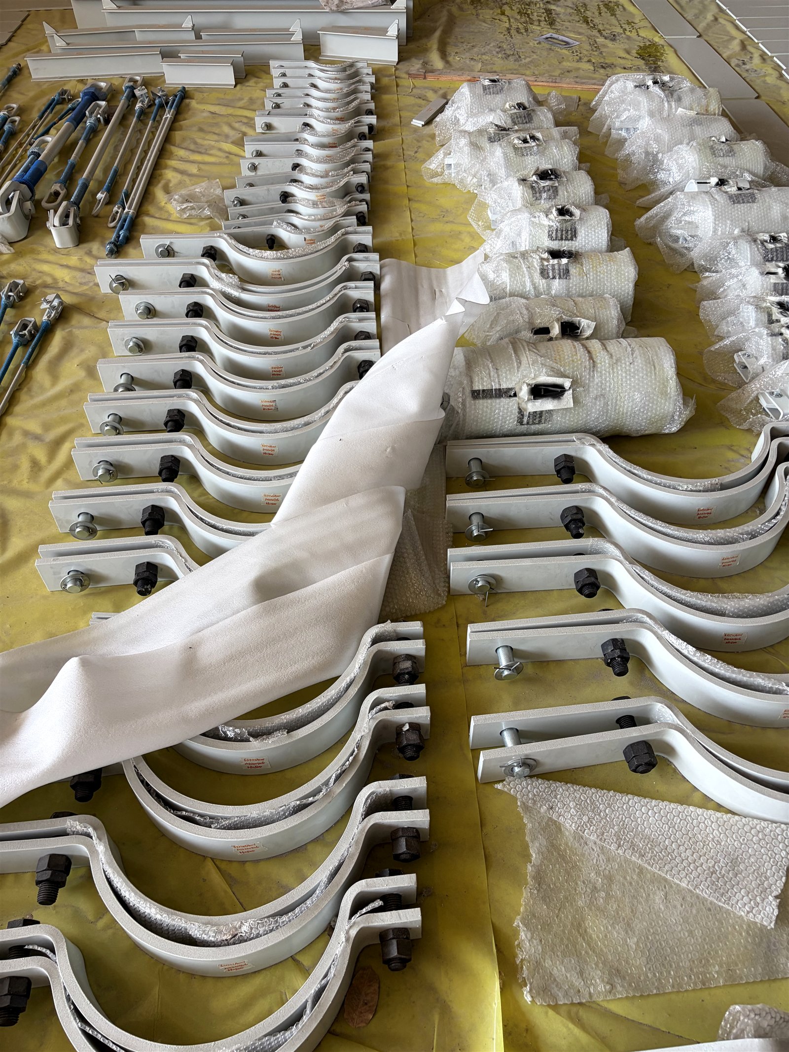
This real factory photograph shows rows of clamp bodies staged indoors. Tags and fitted fasteners are visible, and the repeated arrangement makes general shape and assembly consistency easier to inspect than in a single isolated product image.
From the photograph, a buyer can reasonably observe:
- The general clamp family and body shape.
- The number and position of visible closing fasteners.
- That multiple pieces are staged together.
- That tags are present on visible units.
- The visible condition of the photographed surfaces and assemblies.
The photograph does not establish material grade, coating specification, dimensions, load rating, inspection acceptance, order identity, project identity, packing status or delivery readiness. Those require drawings, records and project documents.
Used this way, a factory image is technical evidence rather than decoration: it helps connect the component names in the article to physical features while keeping claims within what the image actually proves.
Seven checks before comparing quotations
Two quotations are only comparable when they cover the same technical scope. Before comparing price or lead time, check:
- Pattern and drawing: are both suppliers quoting the same component geometry and revision?
- Pipe size or OD: are both using the same controlling diameter?
- Connection scope: are rods, lugs, fasteners or mating parts included consistently?
- Insulation interface: do both quotations treat the pipe/shield/saddle interface the same way?
- Material: is the required component and fastener material identified rather than assumed?
- Finish: is the same project coating or finish requirement included?
- Marking and documents: are tag mapping, certificates requested by the project, packing lists and other documentation included consistently?
This comparison protects the buyer from a false low price created by missing scope. It also gives the supplier a cleaner basis for drawing review and production planning.
Common specification mistakes and their practical consequences
| Mistake | What becomes uncertain | Likely next step |
|---|---|---|
| Selecting from a product photo only | Orientation, connection, dimensions and service inputs | Supplier requests the support detail |
| Giving DN/NPS without pipe system or OD | Physical fit | Confirm pipe specification or actual OD |
| Omitting insulation information | Contact point and required envelope | Confirm insulation and support interface |
| Calling only “two-bolt” or “three-bolt” | Exact body and attachment geometry | Match a drawing or project type |
| Leaving material or finish blank | Commercial scope and fabrication requirement | Quote remains conditional or is revised |
| Mixing drawing revisions | Which requirement controls | Engineering clarification before release |
| Omitting tags | Traceability across schedule, marking and packing | Create a line-item identification map |
These are not merely paperwork issues. Each missing field prevents a like-for-like technical and commercial comparison.
A practical data sheet for a clamp or hanger review
For each line item, use the following structure:
| Field | Entry |
|---|---|
| Tag / item number | |
| Quantity | |
| Pipe orientation | Horizontal / Vertical / TBC |
| Pipe size and specification | |
| Actual outside diameter | |
| Component pattern | Clevis / Two-bolt / Three-bolt / Riser / Project detail |
| Drawing number and revision | |
| Connection arrangement and dimensions | |
| Insulation thickness and interface | |
| Service/design inputs supplied by project | |
| Material and fastener requirements | |
| Finish/coating specification | |
| Marking, documentation and packing notes |
For a wider package-level review, use the Pipe Support Enquiry Checklist. If the information is held in a schedule, How to Read a Hanger Schedule explains how tags, revisions and remarks fit together.
Clevis RFQ fields after the product family is identified
Sometimes the photograph, schedule note or existing context already identifies the item as a clevis hanger. That still does not make the quotation line complete. The remaining task is to connect each commercial line to its controlled tag, quantity basis, drawing revision and mating interfaces.
The official MSS description of ANSI/MSS SP-58-2025 places pipe-hanger work across materials, design, manufacture, selection, application, inspection and installation. An official MSS interpretation page identifies the adjustable clevis as Type 1 and notes that SP-69 has been incorporated into SP-58. These references support the industry terminology and the need for controlled selection inputs; they do not prove that any photographed item complies with a particular edition or project specification.
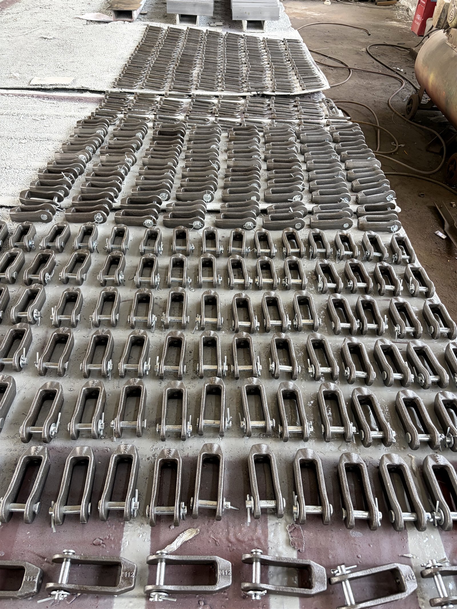
The photograph supports only visible product-family evidence. It does not establish dimensions, pin size, rod connection, material grade, finish specification, allowable load, inspection status or project acceptance. Keep those fields tied to the buyer's drawing, BOM, schedule or approved supplier submittal.
| Clevis RFQ checkpoint | What may be confirmed now | Controlled source still required |
|---|---|---|
| Product family | Clevis family may be identified from the complete support context | Exact pattern follows the drawing, BOM or approved submittal |
| Parent tag / line number | Record the buyer's identifier | Schedule or BOM reference and revision |
| Quantity basis | State piece, set or another buyer-controlled basis | Commercial line or quantity schedule |
| Pipe size / OD basis | Record the supplied value; do not infer it from the image | Pipe specification, drawing or measured value |
| Pin or cross-bolt field | Keep TBC while open | Controlled drawing or approved submittal |
| Inside width / mating interface | Keep TBC while open | Controlled drawing and mating-component details |
| Rod / upper connection | Describe the intended connection chain | Support detail, rod schedule or connection drawing |
| Material and finish | State the project requirement | Project specification and approved supplier offer |
| Linked hardware | State included or separate | BOM scope and quotation exclusions |
| Drawing number / revision | Record both fields on the RFQ line | Current controlled document register |
Copy-ready clevis RFQ block
Use this block in an email, spreadsheet or schedule row. Unknown values should stay visible as TBC.
| Copy into the RFQ | Buyer entry |
|---|---|
| Parent item / tag | |
| Quantity and counting basis | |
| Pipe size or actual OD basis | |
| Clevis pattern / family | |
| Pin or cross-bolt field | TBC |
| Inside width / mating interface | TBC |
| Rod / upper connection basis | TBC |
| Material | |
| Finish | |
| Linked hardware included or separate | |
| Drawing number / revision | |
| Other open fields | TBC |
This block is an enquiry-control aid, not a substitute for engineering selection. It helps the buyer expose missing fields before comparing supplier offers and keeps project-specific requirements separate from what a product photograph can prove.
Frequently asked questions
Is a clevis hanger the same as a pipe clamp?
No. A clevis hanger typically supports a horizontal pipe from an upper rod through a hanger body beneath the pipe. A pipe clamp surrounds or grips the pipe and connects to the remaining support assembly. Confirm the pattern from the complete support detail, not the name alone.
What is the first detail to check when comparing a clevis hanger and a riser clamp?
Check pipe orientation and the structural interface. A clevis arrangement is normally shown with a horizontal pipe and an upper rod connection; a riser clamp is shown around a vertical pipe with lateral arms or lugs bearing on or connecting to the support structure.
Is a three-bolt pipe clamp always stronger than a two-bolt clamp?
Bolt count alone cannot establish strength or allowable load. Compare the verified drawings, dimensions, materials, fasteners, attachment geometry and published design data for the exact patterns being considered.
Can a pipe clamp be selected from DN or NPS alone?
Not reliably in every case. The review may also need the applicable pipe specification or actual OD, the clamp pattern, connection, insulation interface, material, finish and project drawing.
How does insulation affect a clamp or hanger enquiry?
Insulation changes the support envelope and may change which surface the component contacts. Provide the insulation thickness, material and project detail showing whether the support acts at the pipe, shield, saddle or another interface.
Is a product photograph enough to manufacture a replacement clamp?
A photograph can help identify visible features, but it normally does not control dimensions, material, load, connection geometry or coating. Include an existing drawing, measured dimensions and project requirements before treating it as a replacement specification.
What should be marked TBC instead of assumed?
Any field not confirmed by a controlled source: actual OD, pattern, drawing revision, connection dimensions, insulation interface, project loads, material, fastener requirement or finish specification. A visible TBC is easier to close than a hidden assumption.
From technical comparison to a controlled enquiry
The purpose of this comparison is not to push every reader directly into an RFQ. It is to help engineers and buyers identify the right questions before a component is selected or priced.
If you already have a support schedule, BOQ or marked-up detail, compare it against the data sheet above. Keep unknown fields as TBC, attach the controlling drawing and record its revision. You can then review the Pipe Clamps & Clevis Hangers product family or send the technical package for an RFQ review.
For terminology background, see MSS SP-58 Hanger Types Explained, and always apply the edition and requirements specified by the project.