Beam Clamp and Eye Nut RFQ Checklist for Pipe Supports
A beam clamp and an eye nut may appear close together in a pipe-hanger assembly, but the names alone do not establish that the parts will connect to each other—or to the structure and hanger hardware around them. A useful request for quotation identifies each part's position in the connection chain, ties it to a drawing or support tag, defines the mating thread or pin interface, and separates confirmed data from items still marked TBC.
This checklist is for buyers, estimators and project teams preparing enquiries for beam clamps, weldless eye nuts and related pipe-support hardware. It is not a design-selection guide. Final component selection, load verification and structural suitability remain subject to the buyer's approved engineering basis.
Start with the connection chain, not the product name
The fastest way to expose an incomplete enquiry is to sketch the assembly from top to bottom. A simplified chain may look like this:
Structural member → upper attachment → threaded rod or pinned link → intermediate/lower hanger component → supported pipe
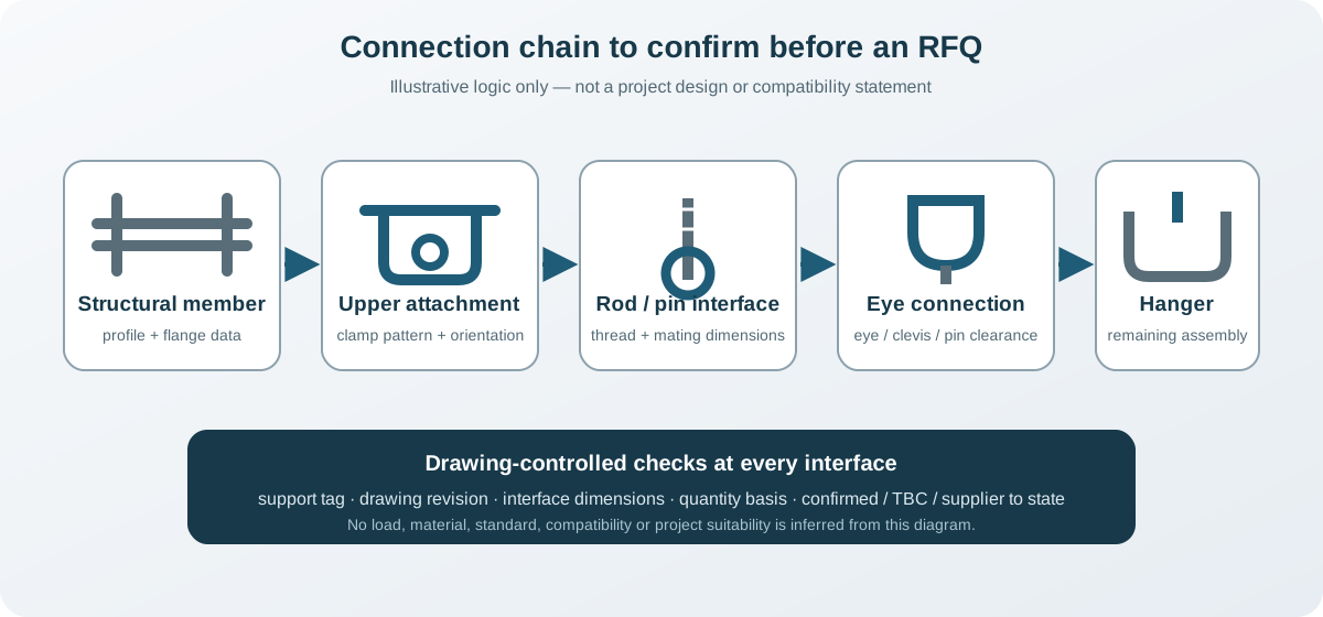
In one drawing, a beam clamp may provide the upper attachment and receive a threaded rod directly. In another, an eye nut may provide a threaded-to-pinned transition elsewhere in the assembly. Some catalogued clamp assemblies include an eye nut; other applications use the two as separate items. The project drawing—not a generic product photograph—must establish the actual relationship.
This distinction matters because a supplier can quote two correctly named components that do not form the intended assembly. A complete enquiry therefore answers three different questions:
- Where does each item sit? Identify the structural member, support tag and adjacent component.
- How does it connect? Define the relevant thread, hole, pin, eye or clamping interface.
- What evidence controls the quote? State the drawing number, revision, schedule line and any buyer-approved design inputs.
If one of those answers is unavailable, keep it visible as TBC. An explicit open field is safer and easier to price than a hidden assumption.
Beam clamp and eye nut: different jobs in the assembly
| Item named in the enquiry | Typical position to confirm | Interface data the supplier needs | What the name does not confirm |
|---|---|---|---|
| Beam clamp | Upper attachment at a structural member | Clamp pattern; member profile and relevant flange dimensions; attachment face and orientation; rod/thread, hole or pin connection; mating accessories | Suitability for the project member, approved load, installation direction, retaining details or compatibility with the next component |
| Weldless eye nut or forged eye nut | Threaded-to-eye/pin transition within a hanger assembly | Thread system and size; right- or left-hand thread when specified; eye/pin mating dimensions; orientation and clearance; mating component reference | That every eye shape or thread will match the clamp, rod, pin or hanger shown in the drawing |
| Combined beam-clamp assembly with eye nut | Upper assembly supplied as a set | Assembly figure or buyer drawing; beam interface; rod thread; included parts; set quantity; finish | That a standalone clamp and standalone eye nut should be priced as the same assembly |
Manufacturer catalogues use different patterns and ordering fields for these products. That variation is a practical reason to quote against the buyer's drawing and interface data instead of substituting by product name alone.
Reconcile three interfaces before requesting a firm quote
1. The structural interface
For a beam-mounted attachment, identify the supporting member and the face on which the item is intended to sit. The useful inputs are usually visible on the approved structural or support detail:
- structural member type or buyer drawing reference;
- relevant flange width and thickness, where the selected pattern depends on them;
- top, bottom or side attachment position;
- expected rod centreline and orientation;
- clamp pattern, set-screw arrangement, cross-bolt arrangement or other connection form shown;
- retaining accessory or secondary part, if the approved detail calls for one.
Do not infer these fields from a site photograph. A photograph can clarify access or orientation, but it is not a dimensional record and cannot replace an approved detail.
2. The mating hardware interface
Follow the assembly to the next component and record the interface between them. Depending on the drawing, this can include:
- thread standard, nominal size and pitch;
- right- or left-hand thread where the design distinguishes them;
- threaded engagement requirement supplied by the buyer or designer;
- pin diameter, usable pin length and retention method;
- eye opening, eye thickness or clevis gap where these dimensions govern the fit;
- required articulation or orientation shown in the assembly;
- which party supplies the rod, pin, nut, washer, link or other mating item.
Never convert a visual resemblance into a compatibility statement. Two parts can both be described as “forged eyes” while having different threads, eye dimensions or intended mating hardware.
3. The document and commercial interface
A technically recognisable item can still produce an uncomparable quotation if the commercial fields are unclear. Keep the following data on the same line as the technical description:
- support tag or assembly ID;
- drawing number and revision;
- item number or buyer figure reference;
- quantity and unit of measure—piece, pair, set or assembly;
- whether fasteners and mating parts are included;
- material and finish as stated in the project documents, or
TBC; - inspection, documentation, marking and packing requirements;
- destination and requested delivery date;
- permitted alternates and the approval route for deviations.
This is especially important when a clamp assembly contains paired jaws, links, an eye nut and fasteners. “20 pcs” can mean 20 individual parts or 20 complete sets; the difference should be resolved before price comparison.
A five-step drawing-to-enquiry workflow
Step 1 — Freeze the reference
Record the drawing number, revision and support tag before extracting dimensions. If the enquiry is based on more than one drawing, list the governing document for each interface. A later revision can change the member, rod size, attachment orientation or item count.
Step 2 — Assign one assembly ID
Give every connection chain a stable assembly ID, even when several purchase lines belong to it. For example, UH-204-A can connect the beam clamp, eye nut, pin and rod lines without relying on adjacent spreadsheet rows.
Step 3 — Separate confirmed values from TBC values
Use distinct columns for Confirmed, TBC and Supplier to state. This prevents an estimator's working assumption from silently becoming a purchase requirement.
Step 4 — Reconcile mating dimensions
Check the interfaces in pairs: beam clamp to member, clamp or eye nut to rod, eye to pin or clevis, and assembly to the next hanger component. Do not check each catalogue item in isolation.
Step 5 — Ask suppliers to expose deviations
Require the quotation to identify any proposed alternate pattern, material, finish, included part or dimensional assumption. A price is easier to evaluate when every deviation is attached to a line item and drawing reference.
Worked example: turn an incomplete line into a quotable record
Consider this intentionally incomplete enquiry line:
> HA-204 | 80 sets | beam clamp + eye nut | finish TBC
It gives a tag, quantity and two names, but it leaves the supplier to guess the connection. Before sending it, the buyer should resolve or flag the following:
| Field | Better enquiry entry | Why it matters |
|---|---|---|
| Governing detail | Support detail SD-204, Rev C | Anchors the item to a controlled reference |
| Structural interface | Member/profile and relevant flange dimensions: see SD-204; supplier to confirm fit against quoted pattern | Prevents a name-only clamp selection |
| Rod interface | Thread system/size: TBC by buyer; no substitution without written clarification | Stops an assumed thread from entering the quote |
| Eye/pin interface | Mating component MC-204; pin and eye dimensions per buyer detail, TBC pending marked-up extract | Preserves the paired relationship |
| Quantity basis | 80 complete assemblies; supplier to list included components | Distinguishes assemblies from loose pieces |
| Finish | TBC—supplier to leave open, not assume standard finish | Keeps an unresolved requirement visible |
| Engineering input | Design load and acceptance criteria supplied separately by buyer/engineer if selection or verification is requested | Prevents the supplier from inventing project criteria |
The improved line is not longer for its own sake. It makes the uncertainty traceable. A supplier can respond with a controlled clarification list instead of embedding assumptions in the unit price.
Compare quotations on the same technical baseline
When bids arrive, compare more than price and lead time. A simple conformity matrix can prevent a low but incomplete quote from appearing equivalent to a complete one.
| Review point | Supplier A | Supplier B | Buyer action |
|---|---|---|---|
| Drawing and revision acknowledged | Yes/No | Yes/No | Reject or clarify an unreferenced quote |
| Beam interface stated | Exact / Assumed / Missing | Exact / Assumed / Missing | Resolve fit-related assumptions |
| Rod or pin interface stated | Exact / Assumed / Missing | Exact / Assumed / Missing | Reconcile mating dimensions |
| Complete set content listed | Yes/No | Yes/No | Normalise the quantity basis |
| Material/finish matched | Matched / Alternate / TBC | Matched / Alternate / TBC | Route deviations for approval |
| Documentation and marking included | Yes/No/TBC | Yes/No/TBC | Confirm deliverable scope |
| Open technical deviations listed | Count + reference | Count + reference | Close before award |
For engineered supports, an “equal” offer is not established by a similar photograph. The quoted pattern and interfaces must be reconciled against the buyer-approved requirements.
What a real factory photo can—and cannot—prove
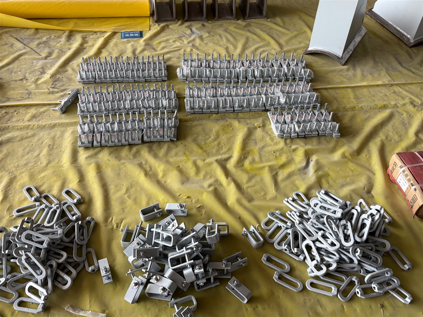
The proposed article image shows groups of metal hanger-attachment components arranged by type in a production setting. It is useful as visual evidence that multiple shapes and connection patterns can look similar when viewed without a drawing.
The image does not establish material grade, finish specification, load capacity, dimensional compliance, inspection status, stock availability or suitability for a particular project. Small labels and cast markings visible in the source image should not be enlarged, transcribed or used as project evidence.
Proposed caption: Grouped forged hanger-attachment components in a factory setting. Final interfaces and supply scope should be checked against the project drawing.
Proposed alt text: Grouped beam clamp and forged eye components arranged in a pipe-support factory
Copy-and-use enquiry data sheet
The following block can be copied into an email or spreadsheet. Keep unanswered fields as TBC.
Project or package reference:
Support tag / assembly ID:
Drawing number and revision:

Item 1 — upper attachment / beam clamp
Buyer figure or required pattern:
Structural member reference:
Relevant flange dimensions:
Attachment face and orientation:
Rod/thread, hole or pin interface:
Included accessories:

Item 2 — eye nut / forged eye
Buyer figure or required pattern:
Thread system, size and handedness:
Mating pin or eye dimensions:
Mating component reference:
Required orientation / clearance:

Common commercial fields
Quantity and unit (piece / pair / set / assembly):
Material requirement or TBC:
Finish requirement or TBC:
Inspection / document requirements:
Marking and packing requirements:
Destination and requested date:
Alternates permitted? If yes, approval route:
Open clarification list:
Before sending, cross-check the schedule against the drawing revision. Our guide to reading a hanger schedule explains how to keep tags, quantities and revisions aligned. For a broader package-level intake, use the pipe support enquiry checklist. Related upper-attachment and rod hardware is grouped on the U-bolts, threaded rods and accessories page.
Frequently asked questions
Are a beam clamp and an eye nut the same component?
No. A beam clamp is an upper attachment associated with a structural member. An eye nut is a threaded-to-eye connection component. They may appear in the same assembly, and some catalogue assemblies combine them, but the drawing must show how they are related.
Can a supplier select the parts from a photograph?
A photograph can help identify the general family and visible orientation. It cannot reliably establish flange dimensions, threads, pin interfaces, approved load inputs or the governing drawing revision. Use it as supporting context, not as the selection basis.
What if the rod thread is known but the mating eye or pin is not?
Record the thread as confirmed and keep the eye/pin fields as TBC. Ask for a marked drawing or dimensional clarification before approving compatibility. Do not treat one known interface as proof that the whole assembly fits.
When should design load be included?
Include the buyer- or engineer-approved design input when the supplier is being asked to select, verify or substantiate a component. Do not ask the supplier to derive project loads from pipe size, a photograph or a generic catalogue description.
How should mixed hardware be counted?
Use an assembly ID and state whether each line is a piece, pair, set or complete assembly. Ask the supplier to list included parts. This keeps paired jaws, links, pins, nuts and rods traceable during quotation comparison and packing review.
Send a controlled package, not a photo-only request
If you are preparing a beam clamp and eye nut enquiry, send the support tag, current drawing, mating-interface data, quantity basis and a visible TBC list. PipeAnchor Supply can review the package for quotation completeness and identify fields that remain TBC; final engineering approval remains with the buyer's responsible design authority. Submit the RFQ package with the relevant drawing extracts and schedule.